|
|
ÉÏšĢĮŌŧŠÐéÄâŌĮÆũžžĘõÓÐÏÞđŦËū SHANGHAI QIEHUA VIRTUAL INSTRUMENT CO.ĢŽLTD |
||||||||||||||||||||||||||||||||||||||||||||||||||||||||||||||||||||||||||||||||||||||||||||||||||||||||||||||||||||||||||||||||||||||
| Home | Company | Product | Download | Guestbook | |||||||||||||||||||||||||||||||||||||||||||||||||||||||||||||||||||||||||||||||||||||||||||||||||||||||||||||||||||||||||||||||||||
|
Wire Rope Non-Destructive Testing (Computerize Magnetic Wire Rope Testing And Diagnosing System) MTC Shanghai Qiehua Virtual Instrument Co., Ltd |
|||||||||||||||||||||||||||||||||||||||||||||||||||||||||||||||||||||||||||||||||||||||||||||||||||||||||||||||||||||||||||||||||||||||
|
1. Abstract The art of wire rope inspection has progressed rapidly during the past few years. Electromagnetic instruments have been developed over the past 90 years. The advancement of Hall Effect sensor and computerization can reliably test wire ropes in service and can remedy the shortcomings of visual wire rope inspection methods. A statistical analysis made in US of over 8000 laboratory and field test records revealed some interesting facts on the condition of wire ropes in services. Approximately 10 percent of all ropes considered showed a strength loss of over 15 percent; more than 2 percent of the ropes had lost over 30 percent of their nominal strength. In other words, while still in service, 10 percent of all ropes were in an unacceptable and potentially hazardous condition, and 2 percent of the ropes were in an extremely dangerous condition. Conversely, more than 70 percent of all ropes in the sample were removed from service with little or no strength loss. This finding suggests that only a very small percentage of all ropes was replaced in a timely manner. 2. Introduction MTC is an Award Winning Non Destructive Testing (NDT) system based on patent pending electromagnetic sensing technology and mathematical model invented by Shanghai Yinhua Wire Ropes Testing Co. Ltd. The combination results a reliable and precise identification and quantitative analysis of the degradation along a rope. The principal deterioration modes of wire rope can be categorized as follows. 2.1 Loss of Metallic Cross-Sectional Area (LMA) Rubbing along floors or other surfaces causes external abrasion. Internal abrasion is caused by nicking, high pressures, or poor lubrication. Corrosion (external and internal) is caused by environmental conditions or poor lubrication. 2.2 Localized Faults (LF) Broken wires are caused by fatigue, plastic wear, martensitic embrittlement, or mechanical damage. Kinks and other mechanical damage may also occur. Although many nondestructive test procedures, employing radiation and optical, acoustical, and mechanical methods, have been proposed and tried in the past, at the present time, only visual and electromagnetic test methods are practical. MTC NDT Wire Rope Testing and Diagnosing System allow simultaneous LMA and LF inspection. The equipment was launched in 1997, and received numerous recommendations from customers, including Shanghai Baosteel Group, Yangtse River Three Gorges Engineering, Shanghai Waigaoqiao Free Trade Zone Stevedoring Co., Shanghai Shipyard, Shandong Shanjiachum Coal Mine, Suzhou Amusement Land, Shanxi Luan Coal Mine, Zhongyuan Oil Field, Shidongkou Power Engineering Co., Tongling Yangtse River Stay-cable Bridge and so forth. Shanghai Yinhua Wire Rope Testing Co. Ltd has a strong R&D team together with the support from Scientific & Techonolgy Research Centre PRC, Shanghai JiaoTong University, Tonggi University and OSC GmbH Germany. 3. Purposes of Nondestructive TestingNondestructive tests in great variety are in worldwide use to: 3.1 Ensure the integrity and reliability of a product. 3.2 Avoid failures, prevent accidents and save human life. 3.3 Make a profit for the user. 3.4 Ensure customer satisfaction and maintain the manufacturerĄŊs reputation. 3.5 Aid in better product design. 3.6 Control manufacturing processes. 3.7 Lower manufacturing costs. 3.8 Maintain uniform quality level. 3.9 Ensure operational readiness. 4. Performance Criteria 4.1 Resolution The resolution of a transducer is measured as the smallest distance between flaws for which the transducer provides distinctly separate flaw indications. Resolving power is defined as the reciprocal of resolution. 4.2 Quantitative Resolution The quantitative resolution is the required minimum length of a uniform flaw for which the sensor provides an accurate quantitative measurement of a ropeĄŊs change of metallic area (CMA) within a predefined small error limit. Quantitative resolving power is defined as the reciprocal of the quantitative resolution. 4.3 Penetration The penetration of a transducer is measured by the ratio of the signal amplitude, caused by an internal flaw, to signal amplitude, caused by an identical surface flaw. This ration is also called the Penetration Ratio. 4.4 Signal to Noise Ratio Only test signal components, which are caused by rope defects, are of interest. That part of the test signal that is not caused by defects is considered as noise. The signal to noise ratio is defined as the amplitude ratio of the defect related signal component to noise. 4.5 Flaw Detectability Flaw detectability is defined as the smallest cross-sectional area change which the sensor can detect. Note that flaw detectability is strictly a function of and intimately related to the signal to noise ratio. A signal to noise ratio greater than one is required for flaw detection. 4.6 Sensitivity The sensitivity is defined as the signal amplitude caused by a pre-determined flaw. In designing rope test instruments, sensitivity specifications are usually meaningless, as it can easily be increased by increasing the gain of the signal amplifier. 4.7 Repeatability Many sensors used for rope inspection are either subdivided or otherwise not rotationally symmetric.Hence, noise as well as flaw signals depends on the angular position of the rope with respect to the sensor head, and complete repeatability of signals cannot be assured for some instruments. 4.8 Magnetic Interference Since insulating materials for magnetic fields do not exist, magnetic flux is difficult to contain. All electromagnetic rope test instruments are surrounded by a magnetic leakage field. Therefore, foreign ferrous objects, such as steel beams, pipes, steel floors, or tightly spaced ropes, in the immediately vicinity of the test instrument can influence the test results. Preventing lateral movement of foreign steel objects ĻC for instance, of adjacent ropes ĻC relative to the sense head eliminates or minimizes problems caused by interference. 4.9 Weight and Size For optimum performance, the magnetizer has to drive the rope into magnetic saturation under all operating conditions. To reduce the weight of the sensor head without sacrificing performance, advanced instruments use ultra powerful rare-earth permanent magnets. 4.10 Operating Convenience For on-site field inspections, the operating convenience of an instrument is very important. Since electric power is not always easily accessible, advanced instruments are battery operated and with distance counter, data acquisition system, user-friendly Man Machine Interface (MMI). 5. Principles of Operation ĄĄ
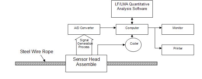
Figure 1 ĄŠĄŠ Functional Block of a MTC NDT Wire Rope Testing & Diagnosing System 5.1 The strong permanent magnets installed in the Sensor Head Assemble supply a constant flux that magnetizes a length of steel wire rope (0.8T) and build up magnetizing circuit as it passes through the sensor head. The saturating magnetic field enables the magnetic sensor to visualize the mechanical anomalies present in the wire rope. The process is somewhat similar to making an NDT examination of a human body with X-rays, where density variations of the patient are made visible by greater or lesser absorption of these rays. 5.2 The magnetic flux leakage created by a discontinuity in the rope, such as broken wire and surface, corrosion, will be focused by the magnetic focus rings and detected by the array Hall effect devices. The local flaw (LF) can then be quantitatively measured. The total axial magnetic flux created by the amount of material missing from location along the wire rope, such as corrosion, deformation, abrasion spots, will be received due to putting the Hall effect sensors on the balance point of magnetic bridge. The loss of metallic cross-sectional area (LMA) can then be also quantitatively measured. 5.4 The coder measured the length of the wire rope under test, and generates continuous pulse to the computer for the recording of distance traveled. 5.5 The Signal Generation Process further enlarge, filter and rectify the detected analogue signal to the A/D converter where it is digitized (12 Bits) and sent to the conjoint computer for data processing and storage.
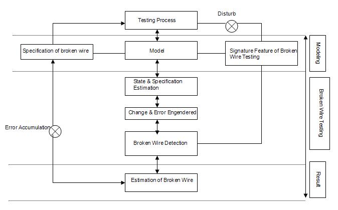
Figure 2 ĄŠĄŠ MTC LF Quantitative Testing Software Basic Module5.6 With intensive Probability of Detection (POD) experiments, MTC envision a set of curves. These curves demonstrate that a certain size discontinuity can be detected with a certain probability at a given confidence level. Base on this statistical concept, test matrices are developed that exercise all potential variable of each test and derive intelligent decision with high level of confidence (ĻR92%). 5.7 A damaged wire rope would generate mutation signal, containing the following information: a) leakage flux around a local fault (LF); b) change in the ropeĄŊs magnetic impedance, due to a loss in the magnetic cross sectional area (lma); and c) change in the magnetic flux value of the magnetic circuit in the sensor head. 5.8 The complex signal generated would be in form of variation of signal peak, wave width and shapes. These signals will be adjusted, and matched by the MTC software together with the pre-set steel wire rope testing parameters. A quantitative estimation result would be generated for verification through the Human Machine Interface. 5.9 Due to complicated construction, manufacturing error and different condition of wire rope, it is recommended that the MTC NDT Wire Rope Testing and Diagnosing System should be used after new installation of the wire rope. The corresponding test record obtained from regular on-going testing should be used to compare with the initial parameters. This practice would bring the system to arrive the most accurate quantitative result. 6. Specifications
6.1 The MTC NDT Wire Rope Testing and Diagnosing System consists of the following items: a) Sensor Head Assembly comprising Magnet Assembly Sensor Assembly Distance Counter Wheel Assembly A/D Converter b) Signal Processing Assembly including Portable computer MTC Wire Rope Testing & Diagnosing (WRTD) Software Universal printer c) Basic Parameters Magnetizing Power > 0.8T A/D Converter 4 ĻC16 channel, 12 bit, 5V ĄĀ10% d.c/20mA Connectors JB1399 Computer CPU 546 or above Internal RAM > 4M 2 serial ports, 1 parallel port Display: SVGA (640 x 480 pixel) or above d) Performance Rope Sizes Ķĩ 1.6 to 200mm Rope Speed 0.003 to 6m/sec Test Signals LF and LMA signal amplitudes Independent of rope speed LF Detection Qualitative Detectability 100% Quantitative Detectability 92% of broken wires Amount of broken wires allow error of one wire independent of wire diameter LMA Detection Quantitative Detectability ĄĀ0.05% of changes of metallic cross sectional area LF/LMA Measure Position ĄĀ2cm of LF/LMA LF/LMA Test Repeatability tendency to 0 Best Gap between Wire Rope 2 to 6mm And Pillow of Sensor Head Environmental Conditions -10 Ąæ to 55 Ąæ (Operating temperature) ĻQ95% (Relative Humidity) 7. Certification, National Award & Patent 7.1 1998, China State Bureau of Technical Supervision authorizes, National Center of Testing Technology, Shanghai, PRC verified and awarded certificate to MTC NDT Testing and Diagnosing System. 7.2 1998, National Science and Technology Research Center, Institute of Scientific & Technical Information of Shanghai, PRC approved MTC performance and functions are international advance and outstrip the standard practice of the American Society for Testing and Materials (ASTM) E1571-96. 7.3 1998, Grade A New High Technology Achievement Certificate awarded by the Government of Shanghai, PRC. 7.4 Theoretical & Methodology Invention Patent: ZL 92115277.9 7.5 Application of MTC Model Patent: ZL 00216937.1 8. Main World Producers of Non-Destructive Magnetic Wire Rope Test Apparatus
APPENDIX A REFERENCES: 1. Dong Xinhua, Kang Yihua, Lu Nanyin Ą°NDT Solution, MTC Novel, Computerize, Dual Quantitative Function, Electromagnetic Wire Rope Testing and Diagnosing SystemĄą 2. Herbert R. Weischedel Ą°The Inspection of Wire Ropes in Services: A Critical ReviewĄą 3. American Society for Nondestructive Testing, Inc. Ą° Introduction to Nondestructive TestingĄą 4. Robert H Grills, Ą° Probability of Detection ĻC An NDT SolutionĄą 5. Health & Safety Executive, UK Ą° Wire Rope Non-Destructive Testing ĻC Survey of Instrument ManufacturersĄą 6. KML Railway Engineering Solutions Ltd. Ą°Wire Rope Non ĻC Destructive TestingĄą ĄĄ |
|||||||||||||||||||||||||||||||||||||||||||||||||||||||||||||||||||||||||||||||||||||||||||||||||||||||||||||||||||||||||||||||||||||||
 |
|||||||||||||||||||||||||||||||||||||||||||||||||||||||||||||||||||||||||||||||||||||||||||||||||||||||||||||||||||||||||||||||||||||||